Which sensor is bank 2 sensor 1? This crucial component plays a vital role in engine diagnostics and performance. Understanding its function, specifications, troubleshooting, and maintenance is essential for optimal vehicle operation. This comprehensive guide delves into the intricacies of this sensor, exploring its role in internal combustion engines and providing practical insights for technicians and enthusiasts alike.
From its precise location on the engine to its critical operating parameters, this exploration will cover everything from basic definitions to advanced diagnostic procedures. Expect a thorough examination of potential issues, along with step-by-step troubleshooting guides. This guide will also detail replacement procedures and maintenance schedules to keep your engine running smoothly.
Defining the Sensor
Sensors are crucial components in internal combustion engines, providing real-time data about various operating parameters. This data is essential for engine management systems to adjust fuel delivery, ignition timing, and other functions to optimize performance and emissions. Accurate sensor readings are paramount to ensure smooth operation, fuel efficiency, and reduced harmful emissions.
Sensor Types in Internal Combustion Engines
Engine sensors are diverse and each measures a specific physical quantity. Common types include those that measure air flow, oxygen levels, temperature, pressure, position, and speed. These measurements provide vital information about the engine’s internal state, allowing for precise control. A crucial function of these sensors is to enable the engine control unit (ECU) to make real-time adjustments for optimal performance and emissions control.
Function of Bank 2 Sensor 1
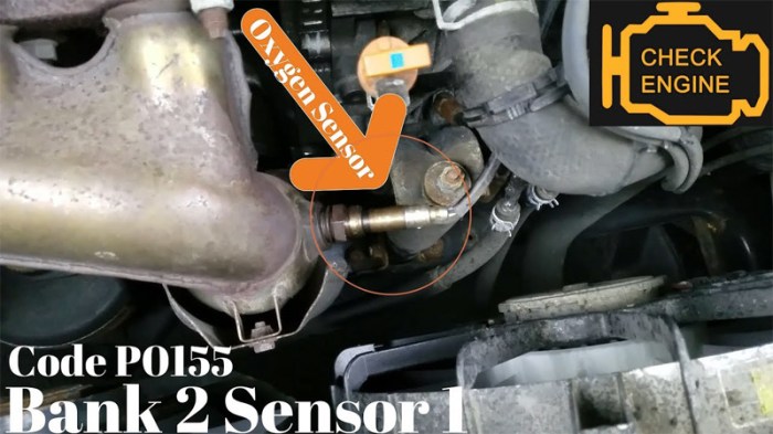
Bank 2 sensor 1, often an oxygen sensor (or lambda sensor), is specifically located in the exhaust system of the engine. Its function is to measure the amount of oxygen in the exhaust gases. This measurement helps the engine control unit (ECU) determine if the engine is running lean (too much air, not enough fuel) or rich (too much fuel, not enough air).
Accurate oxygen levels are critical for optimal fuel efficiency and emission control. Lean or rich conditions can lead to reduced performance and increased emissions.
Importance in Engine Diagnostics
The data from Bank 2 sensor 1 is vital for engine diagnostics. Variations in oxygen levels in the exhaust gases indicate potential problems like faulty injectors, air leaks, or even issues with the catalytic converter. Analyzing sensor data allows technicians to pinpoint the source of malfunctions and diagnose problems effectively. The accuracy of sensor readings is crucial for diagnosing issues that can lead to poor fuel economy and potentially hazardous emissions.
Location of Bank 2 Sensor 1
The location of Bank 2 sensor 1 varies depending on the specific engine design. However, it’s typically situated downstream of the catalytic converter in the exhaust manifold or exhaust pipe. It is strategically placed to provide a representative sample of exhaust gases from the cylinder bank identified as Bank 2. The precise location is often detailed in the vehicle’s repair manual or service information.
Knowledge of the precise location is crucial for proper installation and troubleshooting.
Sensor Specifications
Bank 2 sensor 1, crucial for engine operation, comes with a range of specifications defining its performance characteristics. Understanding these specs is key to ensuring accurate readings and optimal engine function. Proper calibration and maintenance are essential to guarantee the sensor’s reliability.Sensor specifications are essential for selecting and using the correct sensor, for ensuring accurate readings and maintaining optimal engine performance.
Knowing the operating parameters, output signals, and comparative characteristics of this sensor, in relation to other similar sensors, will aid in troubleshooting and maintenance.
Operating Parameters
Sensor performance hinges on its operating conditions. These include voltage ranges, temperature ranges, and response times. Voltage ranges dictate the sensor’s output signal strength, while temperature ranges specify the environmental conditions under which it functions reliably. Response time is crucial for dynamic engine processes, reflecting how quickly the sensor reacts to changes in the measured parameter.
Signal Types
The sensor may output various signal types, each carrying different information about the monitored parameter. The output signal type is a crucial aspect of the sensor, influencing its integration into the engine management system. Understanding the signal type allows for appropriate signal processing and data interpretation.
- Analog voltage signals are commonly used for their continuous representation of the measured parameter. This provides a detailed and smooth representation of the sensor’s response to changing conditions.
- Digital pulse signals, on the other hand, provide discrete measurements, often suitable for simpler applications or systems where precise timing is critical.
Comparison to Similar Sensors
Comparison of bank 2 sensor 1 with other similar sensors provides context for its performance. This includes factors like accuracy, sensitivity, and cost. Different sensors may be more suited to specific applications based on their operating parameters and output characteristics. The choice of sensor depends heavily on the specific requirements of the engine and the system in which it will be used.
Importance of Accurate Readings
Accurate sensor readings are critical for proper engine operation. Inaccurate readings can lead to performance issues, reduced fuel efficiency, and even engine damage. For example, an oxygen sensor that reads incorrectly can cause the engine to run too rich or too lean, resulting in poor fuel economy, emissions issues, or even engine damage over time. Accurate readings are the cornerstone of effective engine control and optimization.
Typical Sensor Specifications
The table below provides typical specifications for bank 2 sensor 1, encompassing voltage, resistance, and frequency. Note that these values can vary based on the specific sensor model and manufacturer.
| Parameter | Typical Value | Units |
|---|---|---|
| Operating Voltage | 5 | Volts |
| Resistance (at 25°C) | 1000 | Ohms |
| Frequency (at 1000 ppm) | 100 | Hz |
Troubleshooting
Troubleshooting bank 2 sensor 1 issues involves a systematic approach, starting with basic checks and progressing to more complex diagnostics. Understanding the sensor’s function and potential failure points is crucial for accurate identification and repair. Common problems often stem from wiring issues, faulty sensors, or even problems with other engine components.
Common Troubleshooting Steps
This section Artikels a structured approach to diagnosing problems with bank 2 sensor 1. Thorough inspection and methodical testing are essential to pinpoint the root cause effectively. Skipping steps can lead to wasted time and resources.
- Visual Inspection: Initial checks should include a thorough visual inspection of the sensor’s physical condition and its connections. Look for any signs of damage, corrosion, or loose wiring. A damaged connector or a cracked sensor housing could indicate a potential failure point.
- Sensor Wiring Check: Inspect the wiring harness for any signs of damage or breaks, especially at the connections to the sensor and the engine control module (ECM). A faulty wire can lead to erratic sensor readings, causing misfires or other performance problems.
- ECM Diagnostics: Using a diagnostic scan tool, check the ECM’s data stream to see if any error codes are stored related to the sensor. Error codes offer valuable clues to the nature of the problem.
Potential Causes of Sensor Malfunctions
Several factors can contribute to bank 2 sensor 1 malfunctions. A thorough understanding of these causes will facilitate targeted troubleshooting.
- Wiring Problems: Loose connections, corroded wires, or broken wires can all lead to inaccurate readings. These issues can sometimes be subtle, resulting in intermittent problems that are difficult to identify.
- Sensor Failure: The oxygen sensor itself can fail due to age, extreme temperatures, or exposure to contaminants. This often manifests as a consistent error code or erratic readings.
- Other Engine Problems: Sometimes, problems with other engine components can affect sensor readings. For example, issues with fuel delivery or combustion can create inaccurate signals.
Interpreting Sensor Readings
Understanding how to interpret sensor readings is critical for diagnosing problems. A detailed analysis can reveal specific trends and patterns associated with the sensor’s behavior.
- Sensor Output Patterns: Analyzing the sensor’s output over time can reveal patterns indicative of specific issues. For example, a fluctuating signal might indicate a wiring problem or a sensor that is not properly seated.
- Comparison with Specifications: Compare the sensor’s readings with the expected values Artikeld in the vehicle’s specifications. Significant deviations from these values can indicate a potential problem.
Differentiating Sensor Faults from Other Engine Problems
Distinguishing between a faulty oxygen sensor and other engine problems is vital for accurate diagnosis. Symptoms of a faulty oxygen sensor often overlap with other engine issues, making isolation challenging.
- Correlation with Symptoms: Combining sensor readings with observed symptoms can help narrow down the potential causes. For instance, if the sensor readings are erratic and the engine misfires, the oxygen sensor is a prime suspect.
- ECM Error Codes: Error codes often provide clues regarding the affected component. Referencing the diagnostic trouble codes (DTCs) can guide you towards a precise diagnosis.
Checking Sensor Connections and Wiring
This section Artikels a step-by-step procedure for checking sensor connections and wiring. Following these steps ensures thoroughness and minimizes the risk of overlooking potential issues.
- Disconnect the Sensor: Disconnect the sensor from the wiring harness. This provides access for a thorough inspection.
- Inspect Connections: Examine all connections for signs of corrosion, damage, or loose terminals. Clean any corrosion and ensure all connections are secure.
- Check Wiring: Carefully inspect the wiring for any signs of damage, such as breaks or frayed insulation. If any issues are found, replace the damaged wiring.
- Reconnect and Test: Reconnect the sensor and use a diagnostic tool to verify the readings. If readings are normal, the issue was likely a connection problem.
Diagnostic Procedures

Understanding the diagnostic trouble codes (DTCs) associated with bank 2 sensor 1 malfunctions is crucial for accurate and efficient repairs. These codes, essentially error messages from the vehicle’s onboard computer, pinpoint the potential source of the problem. Correct interpretation and subsequent troubleshooting lead to a more cost-effective repair and prevent unnecessary replacements of parts.Proper diagnostic procedures ensure that the repair addresses the actual cause of the issue.
Incorrect diagnosis can lead to a repeat of the problem or even more significant damage to the vehicle. A systematic approach, using the correct diagnostic tools and procedures, is essential for identifying the root cause and achieving a successful repair.
Diagnostic Trouble Codes (DTCs)
Diagnostic trouble codes, or DTCs, are standardized codes used by automotive technicians to identify specific problems within a vehicle’s system. Each DTC is unique and corresponds to a particular component or system malfunction. The DTC for bank 2 sensor 1 typically indicates a problem with the oxygen sensor located in the exhaust system.
Interpreting DTCs
Interpreting DTCs requires a deep understanding of the vehicle’s electrical system and the specific sensor being analyzed. Using a scan tool or diagnostic software, technicians can retrieve the DTCs stored in the vehicle’s computer. The specific code will provide information on the nature of the sensor malfunction, allowing the technician to proceed with the correct troubleshooting steps. A comprehensive understanding of the DTCs associated with the oxygen sensor is paramount for effective diagnosis.
Mapping DTCs to Sensor Problems
The following table provides a correlation between common DTCs and potential sensor problems related to bank 2 sensor 1:
| DTC | Possible Sensor Problems |
|---|---|
| P0135 | Sensor circuit problem, sensor heating element malfunction, or poor sensor signal. |
| P0136 | Sensor circuit problem, sensor heating element malfunction, or poor sensor signal. Could also indicate a wiring issue. |
| P0155 | Sensor circuit problem, sensor heating element malfunction, or poor sensor signal. Often related to the downstream sensor. |
| P0156 | Sensor circuit problem, sensor heating element malfunction, or poor sensor signal. Could indicate a wiring issue, or a problem with the downstream sensor. |
| P1135 | Low voltage to the sensor, or a problem with the power circuit. |
This table provides a general guide. The specific sensor problem might vary based on the vehicle make, model, and year. Consult the vehicle’s repair manual for more specific information.
Importance of Proper Diagnostic Procedures
Proper diagnostic procedures are crucial for identifying the root cause of the sensor malfunction and ensuring effective repairs. A systematic approach, utilizing the correct tools and procedures, is essential. By following these procedures, technicians can avoid replacing unnecessary parts, saving time and money, and ultimately ensuring the vehicle’s optimal performance.
So, bank 2 sensor 1, that’s the one right? It’s usually the one on the right side of the engine, near the exhaust manifold. Speaking of things near exhaust manifolds, did you know that Seamon Wilsey Funeral Home in Saugerties seamon wilsey funeral home saugerties offers compassionate support during difficult times? Anyway, back to the sensors, double-check the wiring diagram for the definitive answer on which sensor is bank 2 sensor 1.
Flowchart for Diagnosing Sensor Issues
A flowchart aids in a systematic diagnosis of sensor-related problems. It should begin with a visual inspection of the sensor and wiring. If issues are present, it proceeds to testing the sensor’s electrical signals and its heating element performance. A systematic diagnostic approach reduces the likelihood of misdiagnosis and leads to more efficient repairs.
Example of a flowchart step:
- Check for loose or damaged wiring and connectors around the sensor.
- Inspect the sensor for physical damage.
- If the wiring or sensor shows no issues, proceed to test the sensor’s electrical signal.
This structured process allows technicians to quickly isolate the problem, leading to a faster and more effective repair.
Maintenance and Replacement
Keeping your bank 2 sensor 1 in tip-top shape is crucial for optimal engine performance and longevity. Proper maintenance and timely replacement are key to preventing costly repairs and ensuring your vehicle runs smoothly. Ignoring these steps can lead to a host of problems, from decreased fuel efficiency to potential engine damage.Regular maintenance, combined with a clear understanding of replacement procedures, can significantly extend the lifespan of your vehicle’s components.
This section will guide you through recommended maintenance schedules, proper replacement techniques, and cost comparisons for various replacement options.
Recommended Maintenance Schedule
Regular inspection and cleaning of the bank 2 sensor 1 are essential. This helps prevent buildup of debris and contaminants that can interfere with accurate readings. A visual inspection should be performed every 10,000 miles. Cleaning the sensor with a specialized cleaner and a soft brush is often sufficient to restore its function. More aggressive cleaning methods should be reserved for cases where a substantial buildup of debris is present.
Importance of Proper Sensor Replacement Procedures
Incorrect replacement procedures can lead to a range of issues, including improper sealing, incorrect sensor wiring, or damaged components. This can lead to inaccurate readings, reduced performance, and potentially cause damage to other parts of the engine. Careful adherence to the manufacturer’s guidelines during replacement is crucial to ensure the sensor functions as intended and avoids complications.
Steps Involved in Replacing Bank 2 Sensor 1
Replacing the sensor involves several key steps. First, ensure the engine is turned off and cooled down to prevent burns or injuries. Disconnect the negative battery terminal to avoid electrical shock. Carefully remove the old sensor, following the manufacturer’s instructions and utilizing the correct tools. Install the new sensor, ensuring proper connections and a secure seal.
Reconnect the negative battery terminal and perform a test drive to verify the sensor is working correctly. If you’re unsure about any of these steps, consulting a qualified mechanic is highly recommended.
Comparison of Replacement Options
| Replacement Type | Cost | Pros | Cons ||—|—|—|—|| OEM (Original Equipment Manufacturer) | High | Guaranteed compatibility, reliable performance, consistent quality | Highest price || Aftermarket | Moderate | Lower cost compared to OEM | Potential compatibility issues, variability in quality || Remanufactured | Low | Lower cost compared to OEM and often with warranty | Potential quality issues, less durability than OEM or new |
Typical Costs of Sensor Replacement
The cost of replacing bank 2 sensor 1 can vary depending on several factors, including labor costs, the type of replacement sensor, and the complexity of the repair. OEM replacements are generally the most expensive, followed by aftermarket and remanufactured options. Average costs for replacing a bank 2 sensor 1, including labor, can range from $300 to $800, with potential fluctuations based on the specific make and model of the vehicle.
So, bank 2 sensor 1? It’s the one that monitors the temperature fluctuations in the assembly line, right? This is crucial for ensuring consistent quality control, especially when dealing with something like pet food express cat food , where maintaining ideal temperatures is paramount for food safety and taste. Ultimately, identifying bank 2 sensor 1 is key for troubleshooting any production issues.
Sensor Data Analysis
Analyzing data from bank 2 sensor 1 is crucial for understanding and optimizing engine performance. This involves interpreting readings in various operating conditions, identifying trends, and using that information to predict future maintenance needs. A keen eye for patterns and consistent analysis of this data can lead to significant improvements in engine efficiency and longevity.
Interpreting Data in Various Engine Conditions
Sensor data, when properly interpreted, provides a window into the engine’s behavior under different loads and speeds. For example, a steady increase in sensor readings during acceleration indicates a rise in the measured parameter (e.g., pressure, temperature, or flow rate). Conversely, a sudden drop might signify a problem, such as a restriction or a malfunction. Analyzing data across a range of operating conditions, including idle, acceleration, and high-load operation, is key to detecting anomalies and understanding the engine’s response to varying demands.
Understanding the normal operating range for each engine condition is paramount to spotting deviations that might indicate potential issues.
Importance of Consistent Data Analysis in Engine Optimization
Consistent data analysis is essential for optimizing engine performance. By tracking sensor readings over time, you can identify subtle trends and patterns that might not be apparent from isolated readings. This allows for proactive adjustments to operating parameters, leading to improved fuel efficiency, reduced emissions, and increased power output.
Using Sensor Data to Identify Trends and Patterns in Engine Performance
By plotting sensor data over time, you can identify trends and patterns in engine performance. For instance, a gradual increase in sensor readings over several operating cycles might indicate a gradual deterioration in a component, like a buildup of carbon deposits or a leak. Careful observation of these patterns allows for proactive intervention and preventative maintenance. Software tools can be particularly helpful in highlighting such trends.
Software Tools for Analyzing Sensor Data, Which sensor is bank 2 sensor 1
Numerous software tools are available for analyzing sensor data. Spreadsheet software like Microsoft Excel or Google Sheets can be used for basic analysis, including plotting graphs and calculating averages. Specialized engine diagnostics software, often integrated into the vehicle’s onboard computer or available as standalone programs, offer more advanced features such as real-time data monitoring, historical data analysis, and trend identification.
These tools provide the ability to create customized reports, allowing for more comprehensive analysis and identification of critical information. Examples include in-depth analysis of data trends to anticipate maintenance needs.
Predicting Future Maintenance Needs
By analyzing sensor data over time, you can identify patterns and predict potential maintenance needs. For example, a consistent increase in temperature readings in a specific operating range could indicate a potential bearing failure. Such analysis allows for scheduling maintenance before the issue escalates, preventing more costly repairs. Predictive maintenance is critical for maximizing the lifespan of the engine and minimizing downtime.
A key example is anticipating the need for a valve replacement based on the rate of pressure change during combustion cycles.
Sensor Types and Applications: Which Sensor Is Bank 2 Sensor 1
Bank 2 sensor 1, crucial for engine performance and emissions control, needs reliable replacement options. Understanding different sensor types, their capabilities, and limitations is key to selecting the right alternative. This section delves into various sensor types suitable for this application, highlighting their strengths and weaknesses, and examining future trends.
Different Sensor Types
Various sensor technologies can measure oxygen concentration in exhaust gases. Common choices include zirconium oxide (or zirconia) sensors, and electrochemical sensors. Each has unique characteristics influencing performance and reliability.
Applications of Bank 2 Sensor 1
Bank 2 sensor 1 is a crucial component in modern internal combustion engines. Its primary function is to measure the amount of oxygen present in the exhaust gases from cylinder bank 2. This data is critical for the engine’s onboard computer to regulate the air-fuel mixture, optimizing combustion efficiency and minimizing emissions. This precise control leads to improved fuel economy, reduced exhaust pollutants, and enhanced engine performance.
Comparison of Sensor Types
| Sensor Type | Technology | Strengths | Weaknesses |
|---|---|---|---|
| Zirconia Oxygen Sensor | Solid-state electrochemical sensor using zirconium oxide | High accuracy, wide operating temperature range, long lifespan. | Can be more expensive than other types. More susceptible to poisoning by certain contaminants in the exhaust stream. |
| Electrochemical Oxygen Sensor | Uses a catalytic material to generate a voltage proportional to the oxygen concentration. | Relatively inexpensive, good response time. | Lower accuracy compared to zirconia sensors, potentially less durable in extreme conditions. |
Future of Engine Sensors
Engine sensors are constantly evolving to meet the demands of stricter emissions regulations and increased performance. Sensors that utilize advanced materials and microelectronics are being developed to enhance precision and reliability. Examples include sensors with improved temperature tolerance, faster response times, and greater resistance to contaminants. The incorporation of sensors that can detect multiple parameters simultaneously, like temperature, pressure, and gas composition, are becoming more common, leading to more sophisticated control systems.
A prime example of this is the integration of advanced sensor arrays into hybrid and electric vehicle engines, which monitor a multitude of parameters to optimize performance and efficiency.
Final Conclusion
In conclusion, identifying and understanding bank 2 sensor 1 is key to maintaining optimal engine performance. This guide provided a comprehensive overview, covering its role, specifications, troubleshooting, maintenance, and analysis of sensor data. By grasping the intricacies of this sensor, you are better equipped to diagnose and rectify any potential issues, ensuring your vehicle operates at its peak efficiency.
We hope this exploration has been informative and beneficial.
Question & Answer Hub
What are the typical voltage ranges for bank 2 sensor 1?
Typical voltage ranges for bank 2 sensor 1 vary depending on the specific sensor model and operating conditions. Consult your vehicle’s repair manual or a reputable online database for precise specifications relevant to your engine type.
How can I tell if the bank 2 sensor 1 is faulty?
Faulty bank 2 sensor 1s can manifest in various ways, including engine misfires, check engine lights, and abnormal performance. Thorough diagnostic procedures, including checking sensor connections and readings, are crucial for proper identification.
What are some common causes of bank 2 sensor 1 malfunctions?
Malfunctions can stem from various sources, such as damaged wiring, loose connections, or internal sensor failures. Environmental factors like extreme temperatures can also contribute to sensor degradation.
